Hole location
Define the required position and the following drill diameter.
Hole entry · Location and angle
Spotting and hole-entry preparation before drilling.
A spot drill establishes an entry feature before a subsequent holemaking operation. Specify the following drill as well as the spot geometry. Hole location, entry chamfer and countersink depth are related requirements but should be dimensioned separately.
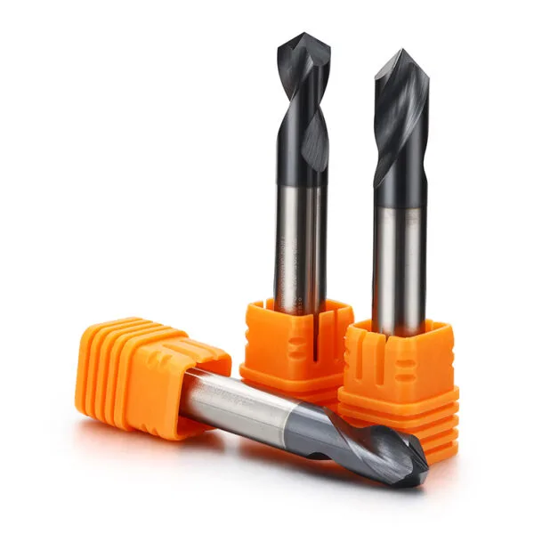
Application guide
Use the part feature and its acceptance requirements to narrow the tool choice.
Define the required position and the following drill diameter.
Compare the spot geometry with the next tool point.
Dimension the chamfer independently if it remains on the finished part.
Selection & configuration
Select the spot angle in relation to the following drill and entry geometry. Confirm whether the requirement is hole location, chamfering or both.
| Decision | What to specify | Why it matters |
|---|---|---|
| Following tool | Drill diameter and point geometry | The spot must suit the next cutting operation. |
| Spot feature | Angle, diameter and depth | These establish what remains at the hole entry. |
| Part surface | Flat, curved or inclined entry | The approach condition changes the process review. |
Swipe the table to compare all columns →
Include these details so the tool dimensions and application can be reviewed together.
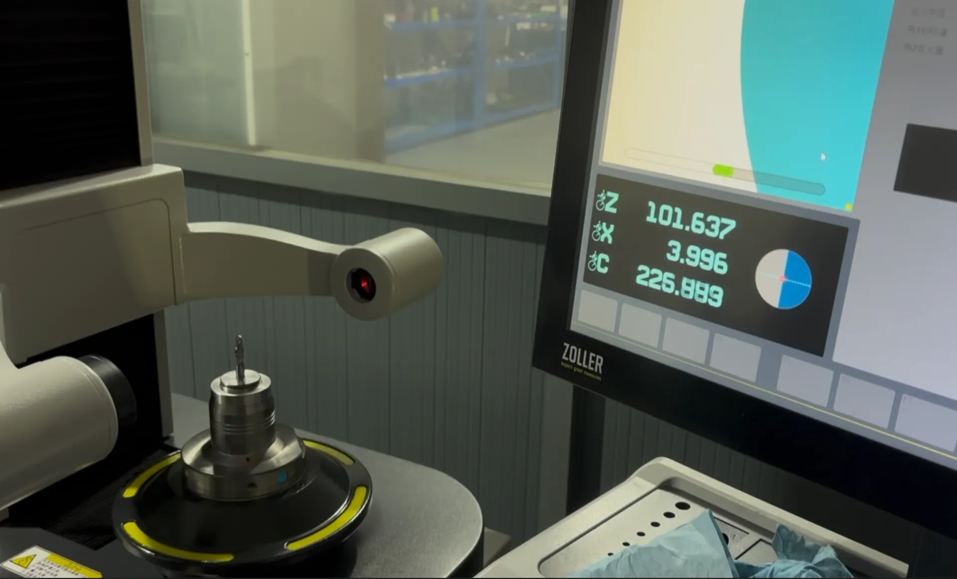
From drawing to inspection
A tool specification should describe both the cutting geometry and the acceptance requirements. Mark critical dimensions on the drawing and discuss how they will be checked before ordering.
Selection questions
Practical answers for carbide spot drills.
It can be reviewed for that purpose, but the final chamfer dimensions and the following drill geometry must both be specified. Locating a hole does not automatically define its finished chamfer.
Hole diameter; depth; material grade; entry and exit geometry; tolerance; coolant system. Add the quantity and delivery destination. A drawing or marked part section helps identify critical dimensions and clearance constraints.
The quotation and agreed drawing define the tool configuration, inspection scope, quantity and delivery schedule. Reference images show the tool family; use the confirmed specification for ordering.
Start with your application
Send your drawing or machining requirement. Your selected tool category and a checklist will be carried into the inquiry form.