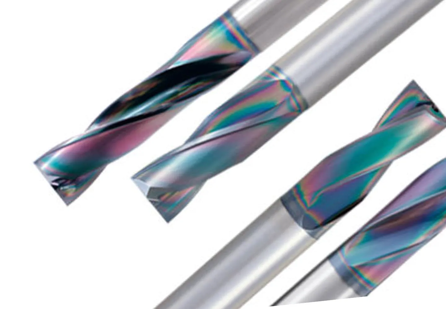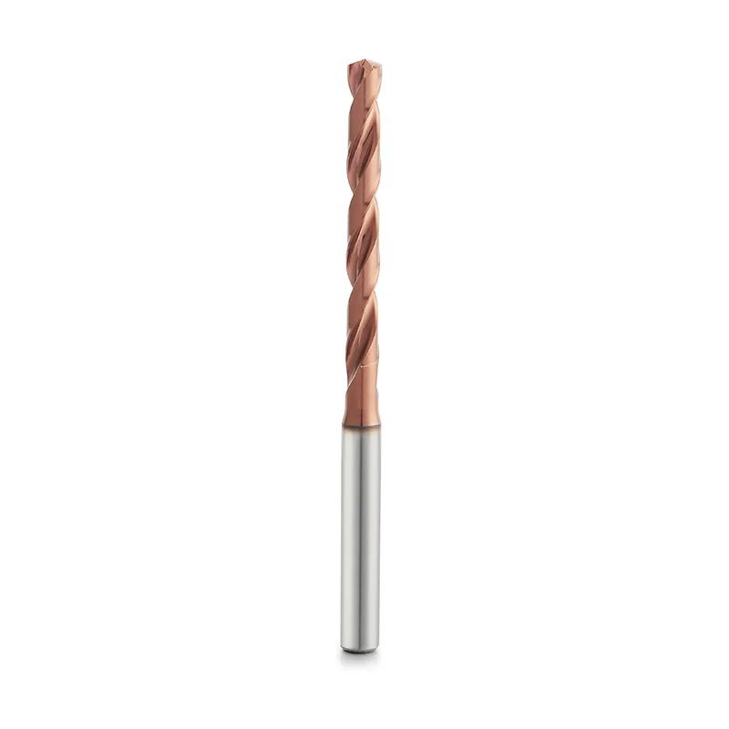
External-Coolant / Solid Carbide Drills
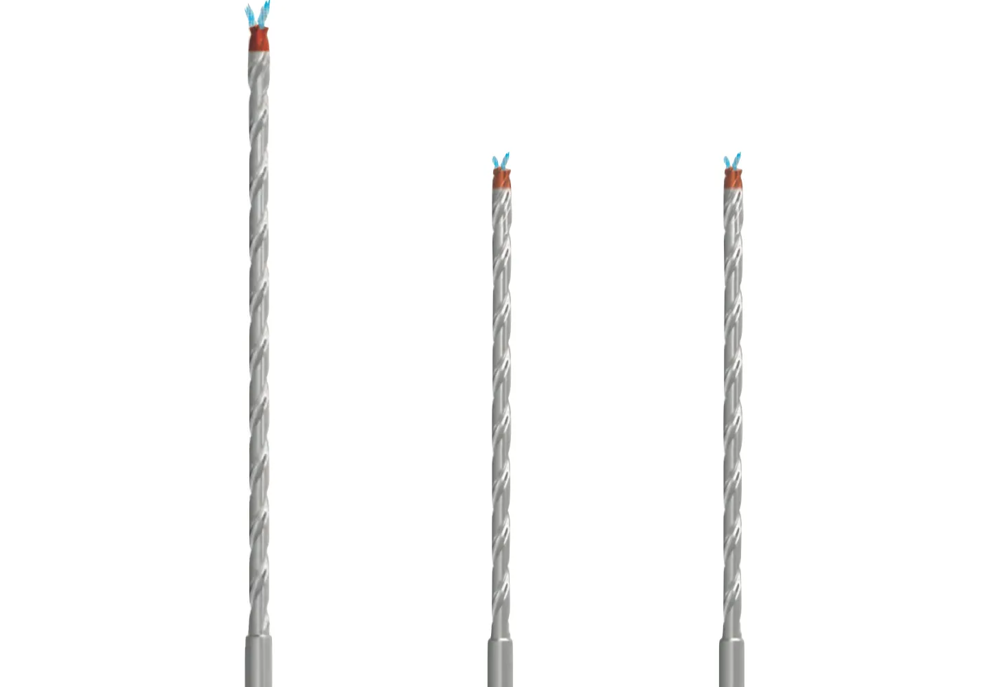
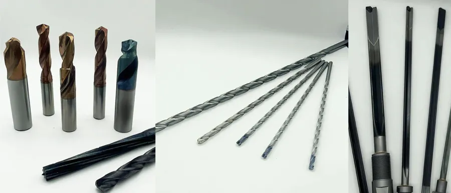
Rigid drilling with coolant delivered from outside the tool.
View tool range →Holemaking · Depth, entry and coolant
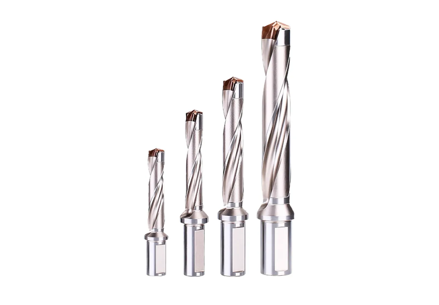
Compare solid carbide, coolant-through, spot, step and long-reach drills, alongside existing modular and flat-bottom drilling ranges.
Drill selection starts with the hole rather than the coating. Specify diameter, depth, entry surface and whether the hole is blind or through. Then compare external-coolant, internal-coolant, spot, step and modular options against the material and machine.
Explore the family
Compare the feature each tool solves, then open the relevant range for application and ordering details.
Rigid drilling with coolant delivered from outside the tool.
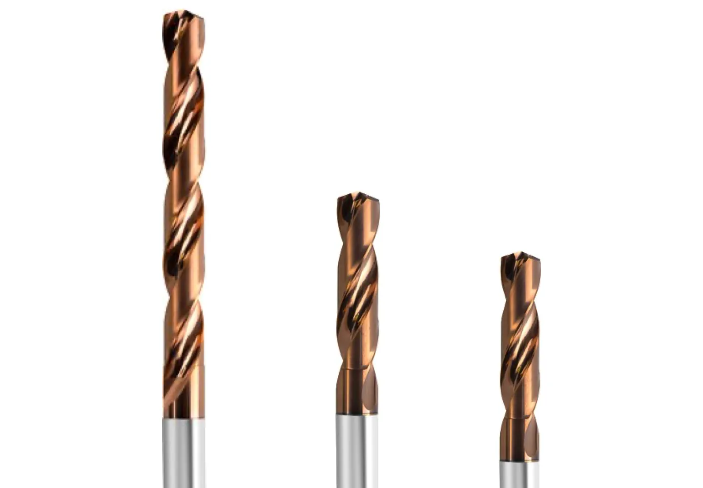
View tool range →Coating and geometry selection for drilling aluminum alloys.
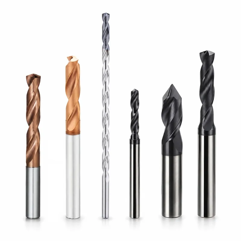
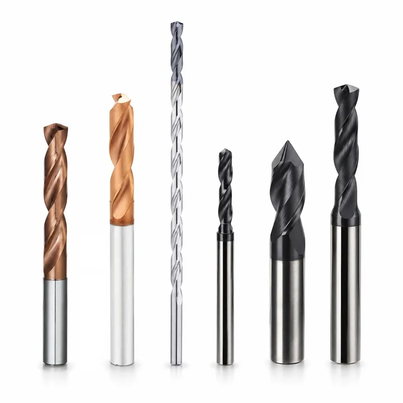
KY TOOLS range illustration. The exact tool geometry and coating are confirmed with your specification.
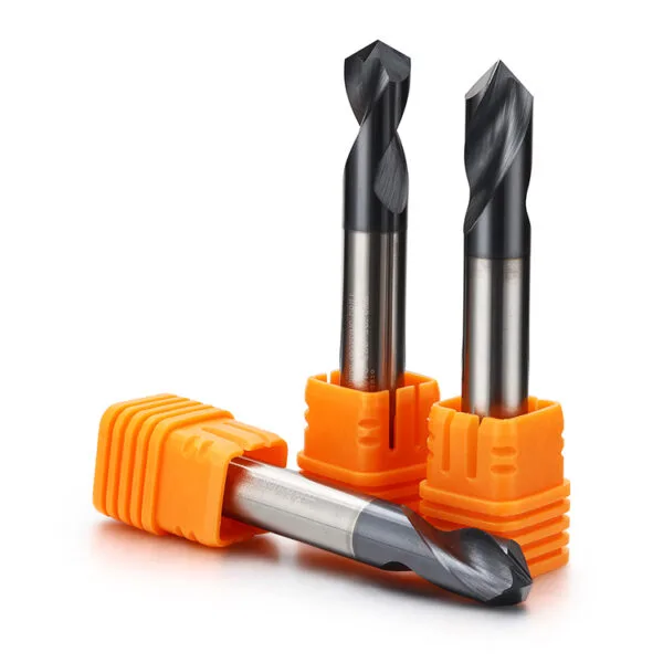
View tool range →Multiple hole diameters or a hole and chamfer in one tool.
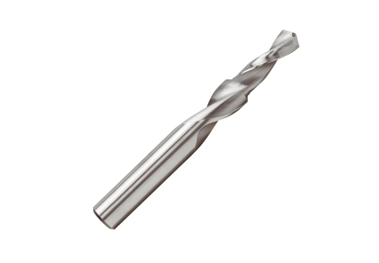
View tool range →Drilling where fixtures, part features or hole depth require extended reach.
KY TOOLS range illustration. The exact tool geometry and coating are confirmed with your specification.
View tool range →Application guide
Use the part feature and its acceptance requirements to narrow the tool choice.
Review repeatability requirements and the planned downstream finishing process.
Dimension the axial relationship between the hole, counterbore and chamfer.
Separate hole depth from the extra length needed to clear fixtures.
Application & selection
Use the drawing and actual machining conditions to define a configuration for this tool family.
Give the required cylindrical depth separately from the total drilled depth. Identify blind and through holes and mark any bottom-shape requirement. Point geometry and bottom clearance can affect whether the usable hole meets the drawing.
Show angled faces, cross holes and interrupted exits. Include any pilot or spot operation already planned. Entry preparation should be reviewed with the chosen drill geometry rather than assumed necessary or suitable for every tool.
State whether coolant is available through the spindle and tool, or only externally. Include machine limitations and hole access. An internal-coolant drill requires a compatible supply arrangement; its presence in the catalog does not establish compatibility with every machine.
Separate the drilled depth from extra length required to clear fixtures or adjacent geometry. Provide the holder envelope and a section of the setup. A long assembly should solve a demonstrated access need.
Application & selection
Use the drawing and actual machining conditions to define a configuration for this tool family.
Compare the required diameter, depth and production setup before choosing a solid or replaceable-tip system. Include holder and interface requirements for modular options. A change in tool structure should be reviewed against the existing machine and process.
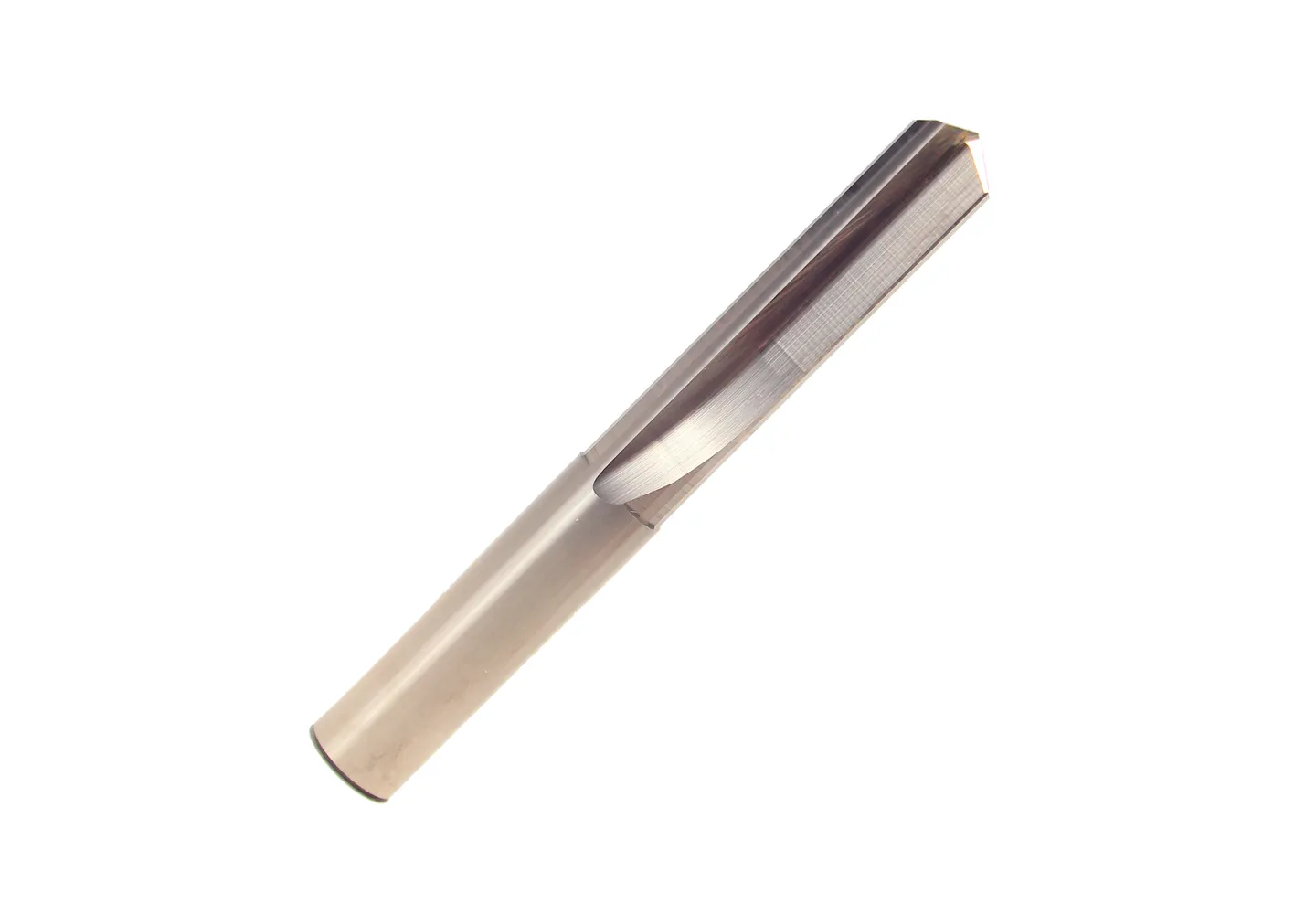
Dimension each diameter, axial step and bottom requirement. State whether the tool enters solid material or follows an existing hole. This distinguishes a combined stepped operation from finishing an already prepared feature.
Identify whether size, position, finish or a downstream operation controls the result. If reaming or another finishing step follows, include its stock requirement. The drill request should explain what must be left for the next tool.
Selection & configuration
Choose the drill from hole depth-to-diameter ratio, entry and exit geometry, workpiece material and coolant access. Deep holes need a validated chip evacuation and entry strategy.
| Decision | What to specify | Why it matters |
|---|---|---|
| Hole geometry | Diameter, depth and entry/exit conditions | Cross holes and inclined surfaces can change the process review. |
| Coolant | Delivery, pressure and filtration | The available system must match the selected drill construction. |
| Final requirement | Size tolerance and surface finish | Some holes require a separate reaming or finishing operation. |
Swipe the table to compare all columns →
Include these details so the tool dimensions and application can be reviewed together.

From drawing to inspection
A tool specification should describe both the cutting geometry and the acceptance requirements. Mark critical dimensions on the drawing and discuss how they will be checked before ordering.
Selection questions
Practical answers for carbide drills.
Not necessarily. Compare hole depth, chip evacuation, material and the coolant system available. An internal passage is useful only when the holder and machine can supply the intended delivery.
Hole diameter and depth; through or blind hole; material; tolerance; coolant pressure; entry condition. Add the quantity and delivery destination. A drawing or marked part section helps identify critical dimensions and clearance constraints.
The quotation and agreed drawing define the tool configuration, inspection scope, quantity and delivery schedule. Reference images show the tool family; use the confirmed specification for ordering.
Start with your application
Send your drawing or machining requirement. Your selected tool category and a checklist will be carried into the inquiry form.