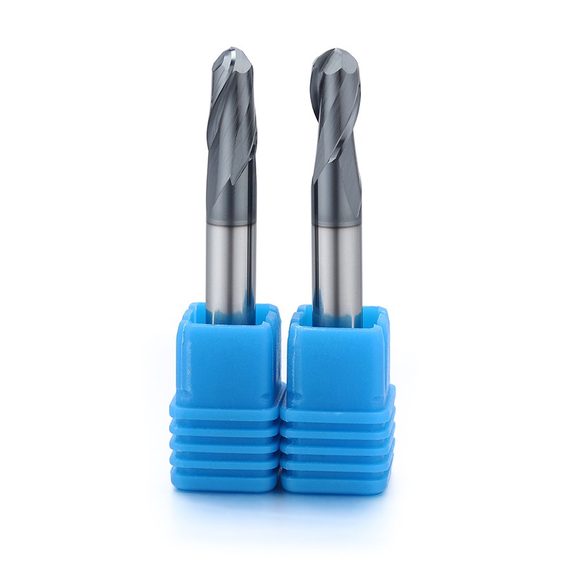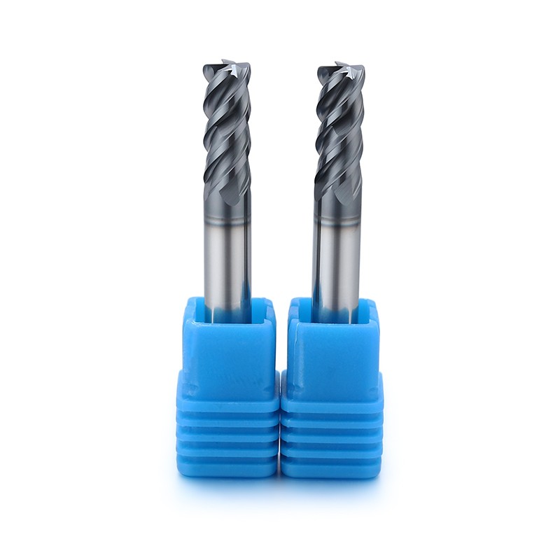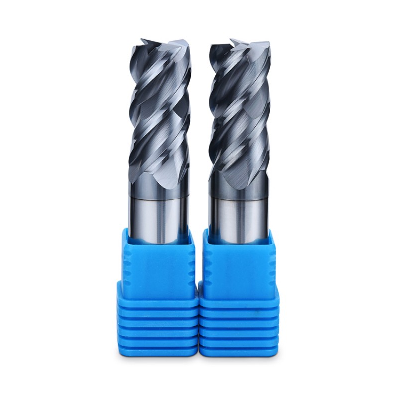
Carbide Square End Mill For Stainless Steel
For stainless-steel walls, shoulders and slots. Include the exact grade, engagement and chip-removal conditions.
Request a quote →Stainless alloys · Engagement and chip control
Pocketing, profiling and shoulder milling in stainless alloys.
Stainless-steel tool selection needs the alloy grade and process conditions together. Enclosed pockets, thin walls and long reach place different demands on the cutting edge. Describe where chips are trapped and where the part loses rigidity before selecting the flute configuration.
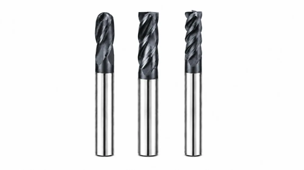
Choose the cutting profile
Choose a profile for the feature you need to machine, then request dimensions and application support for this stainless steel series.
For stainless-steel walls, shoulders and slots. Include the exact grade, engagement and chip-removal conditions.
Request a quote →For contoured stainless components. Describe surface access, finishing allowance and the critical inspected areas.
Request a quote →For pocket floors and corner transitions in stainless parts. Include the fillet size and any interrupted features.
Request a quote →Application guide
Use the part feature and its acceptance requirements to narrow the tool choice.
Assess chip evacuation at the deepest point, not only at the pocket opening.
Review part support and finishing sequence where the workpiece can deflect.
Match cutting length to the wall while keeping unnecessary overhang out of the setup.
Application & selection
Stainless steel is a material family with different workpiece conditions, not a single tool specification.
Send the exact grade from the drawing or material certificate, along with the supplied condition and hardness if known. Include any treatment performed before milling. A familiar alloy name alone does not describe every production condition.
Describe the surfaces left by earlier machining, forming or repair work. If a trial has already been made, retain its cutting parameters and photographs. The application review needs the condition encountered by the current tool, not only the original stock.
Show enclosed pockets, narrow slots and areas where chips can collect. State how coolant or air reaches the cutting zone and whether the holder obstructs delivery. The intended removal method is part of the setup description.
Application & selection
Use feature geometry and the operation sequence to separate tool requirements.
Identify radial engagement and the entry method. A closed slot and an open side cut expose the tool to different conditions. Include the planned path instead of describing both operations only as milling.
Mark the unsupported wall height and the clamping arrangement. Describe the order in which adjacent material is removed. Acceptance measurements should identify where the part is supported during inspection.
For ball nose finishing, supply the required contour, minimum internal radius and remaining stock. Note transitions where tool access changes. This allows the cutting profile and reach to be reviewed against the actual part.
Mark edges where burrs or later deburring affect the finished component. Include the direction of access for those edges and whether they are functional or cosmetic. Define the acceptable condition with a drawing note or example.
Application & selection
Useful trial records connect a visible result to the conditions that produced it.
Include tool dimensions, holder, overhang, workholding, cutting parameters and coolant delivery. Mark where edge damage or poor finish first appears. A photograph without the location and setup can leave several different causes unresolved.
Record the critical dimensions and surface result using the agreed method. Separate burr condition from surface roughness and dimensional error. Each observation should refer to a particular feature on the part.
Retain the accepted tool drawing and material condition with the purchase reference. List quantities by profile and size, and include any identification requirements. This helps keep the tool request consistent with the process that was evaluated.
Selection & configuration
Avoid repeated rubbing and chip recutting. Stainless grades differ in work hardening and chip behavior, so coating, edge preparation and coolant should be evaluated together.
| Decision | What to specify | Why it matters |
|---|---|---|
| Alloy grade | Exact stainless designation and condition | Different stainless families respond differently to cutting. |
| Coolant access | Delivery method and access to the cutting zone | A nominal coolant supply may not reach an enclosed cut. |
| Part rigidity | Wall thickness, clamping and unsupported areas | A rigid cutter cannot compensate for a moving workpiece. |
Swipe the table to compare all columns →
Include these details so the tool dimensions and application can be reviewed together.
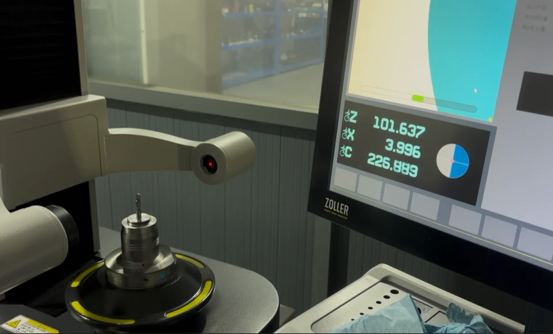
From drawing to inspection
A tool specification should describe both the cutting geometry and the acceptance requirements. Mark critical dimensions on the drawing and discuss how they will be checked before ordering.
Selection questions
Practical answers for end mills for stainless steel.
An enclosed feature changes coolant access and chip escape. Include its depth, entry strategy and remaining wall thickness; a successful open-side cut does not establish a pocketing process.
Stainless grade; coolant method; pocket depth; engagement; chip evacuation limits. Add the quantity and delivery destination. A drawing or marked part section helps identify critical dimensions and clearance constraints.
The quotation and agreed drawing define the tool configuration, inspection scope, quantity and delivery schedule. Reference images show the tool family; use the confirmed specification for ordering.
Start with your application
Send your drawing or machining requirement. Your selected tool category and a checklist will be carried into the inquiry form.